Information about the DUTlink board, how to use it and how to connect it to your DUT.
The dutlink-board is a test harness designed for Jumpstarter, it’s a board in micro ITX
format, which allows mounting of a DUT on top, and enables the usage of standard rack or desktop
server cases.
The dutlink-board is an Open Hardware project, you can find the design files in the
DUTlink board repository, a first batch
was built by SeeedStudio using their fusion PCB service, and you can find the manufacturing files
here.
High level overview
A device under test (left side) is connected to the dutlink board, which is connected to a
host (right side) via USB-C. The host runs the jumpstarter software, which allows CI to
interact with the DUT, controlling the power, connection and management of a storage device
(see the pendrive in the next pictures), and communication via serial console.
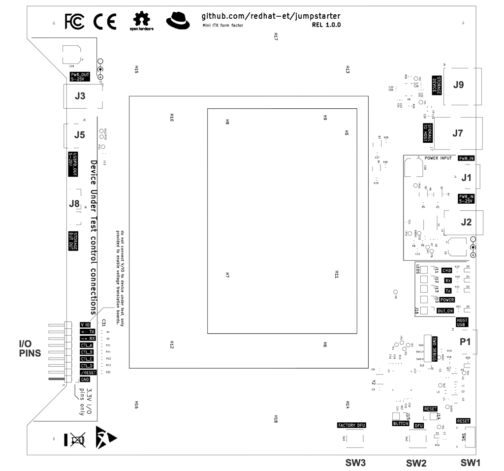
This is how the hardware looks
Top view of the dutlink board REL-1.0.0
On the left area: you can see connections to the Device Under Test
On the right, you can see the connections to the testing
host, where the jumpstarter software runs.
Top view of the dutlink board REL-1.0.0 with a visionfive2 board attached
via USB-PD power pass-through. See more details in the visionfive2 section.
Warnings: read before you use the board
Barrel power connectors and USB-PD power pass-through
CE and FCC certification is still pending (the labels on the board are still incorrect). This is a still a prototype, and it has not been certified yet.
Barrel power connectors have a polarity, with the positive pin in the center, and the negative pin on the outside. If you connect the barrel power connector with the wrong polarity, you will damage the board.
USB-PD power pass-through and Barrel power should not be used at the same time, as this will damage the board or your power adapters.
Digital signals on the I/O connector are 3.3V only
The I/O connector has digital signals, but they are 3.3V only, this is generally ok if you use 0 or HiZ outputs,
but never use a HI/H/1 signal on an output when the target device is only 1.2, 1.8 or 2.5V, as this could damage the device.
Outputs are protected with a 100 ohm resistor which would avoid damage in most cases.
The V IO pin is provided to enable the use of voltage translation circuits if necessary.
Known issues and limitations
USB-C connections
USB-C connections are reversable, but in the 1.0.0 version of the board, the USB-C receptacles have not been wired properly, so in some cases you may need to flip the USB-C cable to get the connection or power working, this applies to all USB-Cs on the board.
i.e.:
dutlink-board is not being detected by the host: try flipping the USB-C cable.
the device is not powered-up or charging: try flipping the power USB-C cable.
Storage DUT Out connector is fragile
The USB storage connector used to connect to the DUT is fragile, avoid pressing up or down
from the cables or connectors once attached to the board, as this could rip the connector
from the board. Once the board is tested glue could be carefully applied to the back of the connector.
1 - Orin NX Devkit + DutLink
Manual for connecting the dutlink board to the Orin AGX devkit.
This is a graphical guide describing how to connect an NVIDIA Orin AGX Devkit
to the dutlink-board.
This setup will use 4 USB connections to your host:
Jumpstarter control
Jumpstarter USB3 storage
NVIDIA Flashing USBC or microUSB port
Wiring table
Name
NX Devkit Connector
Jumpstarter Connector
Host connector
Comments
GND
(J14) pin 7
(I/O) GND
Connecting signal ground
/FORCE_REC
(J14) pin 10
(I/O) CTL_A
Force recovery mode signal (active low)
SLEEP/WAKE
(J14) pin 12
(I/O) CTL_B
Power down [>10s], Power up [short] (active low)
/SYS_RESET
(J14) pin 8
(I/O) RESET
Reset signal (active low)
RCM
(J5) USB-C or microUSB connector
USB
NVIDIA Flashing interface for RCM
DUT-STORAGE
(J7-J6) USB 3.2 Gen1
J8
USB storage attachment to DUT
DUT-POWER
POWER JACK
J3
Power output for the DUT
ETHERNET
Ethernet
Connect to a network where the host is also connected
JUMPSTARTER
P1 USB-C
USB
Jumpstarter control USB bus, used by the jumpstarter software to talk to the
dutlink-board
HOST-STORAGE
J7 USB-B 3.0
USB
Host access to USB storage, used to write the USB disk
DISK
J9 USB-A 3.0
Connect a pen-drive or disk here. USB3.1 Gen1 (5Gbps recommended, Gen2 10Gbps don't work well yet)
POWER-4-DUT
J2 BARREL JACK POWER
Connect the Orin NX Devkit power adapter here
Troubleshooting
My console doesn’t show anything
See the Console access section and clear any previous configuration for the USB console.
The system won’t boot from the USB disk
You need to go into the UEFI BIOS and change the boot order to setup “new devices”
as the first boot option. Make sure that the USB devices is found.
Make sure that you are not using a USB3.1 Gen2 device (10Gbps), as this is not supported yet.
This means that we will use the power control directly, without using the power button as it’s not necessary for this
board. The flashing mode is activated by setting force recovery signal to low aL, then asserting reset rL, and then
waiting for 1 second w1, then releasing the reset signal rZ, waiting another second w1, and then releasing the
force recovery signal aZ.
Console access
The Orin NX Devkit the UEFI console only on the 40pin port, so any necessary UEFI settings must be performed
on that port first.
You must clear the previous usb console settings if this board was used with an AGX
$ jumpstarter set-usb-console orin-nx-00 ""
2 - Connector reference
Connector reference for te dutlink-board
Device Under Test connections
Power
Connector
Definition
J3
J3 is a barrel jack connector that provides power output to the DUT. The source
of the power comes from J1.
Warning: Do not use at the same time as J5 or J2.
J5
J5 is a USB-C connector that provides power output to the DUT. The source of the
power comes from J2, USB-PD negotiation is connected to the power adapter on J2. USB-PD is a standard that allows negotiation of the voltage and current.
Warning: Do not use at the same time as J3 or J1.
Storage
Connector
Definition
J8
J8 is a USB3 micro B connector for storage. This connector provides access to
the storage device that is connected to J9.
One possible cable you can use in this connector is this one: link
I/O pins
The I/O pins connector provides a 3.3V digital interface to the DUT, or any surrounding
test hardware (like video signal generators, sensor emulators, or other elements).
Never use a HI/H/1 signal on an output when the target device is only 1.2, 1.8 or 2.5V, as this could damage the device.
Outputs are protected with a 100 ohm resistor which would avoid damage in most cases.
The V IO pin is provided to enable the use of voltage translation circuits if necessary.
Pin
Definition
V IO
Provides a voltage reference for a voltage translation circuit
TX
Provides an output UART to the DUT, this is connected to the jumpstarter console.
RX
Provides an input UART from the DUT, this is connected to the jumpstarter console.
CTL_A
Provides a digital input/output which can be controlled by the jumpstarter software.
The current convention is to use this pin for forcing devices into flashing mode,
but it can be used for any purpose.
CTL_B
Provides a digital input/output which can be controlled by the jumpstarter software.
CTL_C
Provides a digital input/output which can be controlled by the jumpstarter software.
CTL_D
Provides a digital input/output which can be controlled by the jumpstarter software.
/RESET
Provides a reset output signal which can be controlled from the jumpstarter
software. It's active low open collector output, this means that it will output
a '0' when the reset is asserted, and it will be in HiZ when the reset is not.
Power input connections
Connector
Definition
J1
J1 is a barrel jack connector where the power adaptor for the DUT must be connected. The
destination of this power is J3.
Warning: Do not use at the same time as J5 or J2. And please note that the center
pin is the possitive connection, power cannot be inverted.
J2
J2 is a USB-C connector that receives power for the DUT from the power adapter. The
destination is J5, USB-PD negotiation is connected between J2 and J5. Please note that
there is a bug in the 1.0.0 version of the board, and the USB-C receptacle is not wired
properly, so in some cases you may need to flip the USB-C cable to get the connection or
power working, this applies to all USB-Cs on the board.
Warning: Do not use at the same time as J3 or J1.
Host connections
Connector
Definition
P1
P1 is a USB-C connector that provides power and control to the Jumpstarter microcontroller,
once this is connected to the host jumpstarter must be detected by the kernel and a ttyACM device
must be detected.
J7
J7 is a USB3 B connector. This connector must be connected to the host, and it provides
access to the storage device connected to J9. One possible cable you can use in this
connector is this one: link
Other/notes
While not technically a part of the dutlink board, some DUTs need USB host
access to allow flashing from the host, i.e. NVIDIA Jetson boards. In some
cases multiple USB connections.
Storage Device
Connector
Definition
J9
J9 is a USB3 A connector, in this connector a storage device must be connected,
this device will be multiplexed between the host and the DUT. The HOST can flash
it, and the DUT can boot or install from this device.
Flashing speed will hugely depend on the storage device used, and while the
dutlink-board has been designed for 10Gbps USB3.2 Gen2, the speed will
depend on the storage device used as well as the cables connected to J8 and J7.
To stay on the safe side 5Gbps devices are recommended. One possible device
you can use for this purpose is: link
Manual for connecting the dutlink board to the Orin AGX devkit.
This is a graphical guide describing how to connect an NVIDIA Orin AGX Devkit
to the dutlink-board.
This setup will use 4 USB connections to your host:
Jumpstarter control
Jumpstarter USB3 storage
NVIDIA TOPO USB Controller
NVIDIA Flashing USB port
Wiring table
Name
AGX Connector
Jumpstarter Connector
Host connector
Comments
GND
(J42) pin 1
(I/O) GND
Connecting signal ground
/FORCE_REC
(J42) pin 2
(I/O) CTL_A
Force recovery mode signal (active low)
/POWER
(J42) pin 3
(I/O) CTL_B
Power down [>10s], Power up [short] (active low)
/RESET
(J42) pin 4
(I/O) RESET
Reset signal (active low)
AUTO-POWER
J42 / pin 5 to 6 jumper
Auto power-on jumper must remain connected
RCM
(10) USB-C connector
USB
NVIDIA Flashing interface for RCM
TOPO Console
(9) USB Micro B conn
USB
NVIDIA TOPO interface (consoles and boardctl)
DUT-STORAGE
(12) USB 3.2 Gen1
J8
USB storage attachment to DUT
DUT-POWER
(4) Power USB-C
J5
Power output for the DUT
ETHERNET
(6) Ethernet
Connect to a network where the host is also connected
JUMPSTARTER
P1 USB-C
USB
Jumpstarter control USB bus, used by the jumpstarter software to talk to the
dutlink-board
HOST-STORAGE
J7 USB-B 3.0
USB
Host access to USB storage, used to write the USB disk
DISK
J9 USB-A 3.0
Connect a pen-drive or disk here. USB3.1 Gen1 (5Gbps recommended, Gen2 10Gbps don't work well yet)
POWER-4-DUT
J1 USB-C PD
Connect the Orin AGX Devkit power adapter here
Troubleshooting
My console doesn’t show anything
See the Console access section and associate the TOPO USB console to your board.
My DUT doesn’t power on
Check that the AUTO-POWER jumper is connected.
See Know issues and limitations you may need to flip the USB-C cable going to the AGX board or the power adapter USB-C.
My console shows garbage during boot
There is a known issue with the TOPO USB console, where it will show garbage after power-on, then it
recovers. To avoid this issue, we recommend using jumpstarter firmware > 0.06 and
configuring the power sequencing as described in Power sequencing.
The system won’t boot from the USB disk
You need to go into the UEFI BIOS and change the boot order to setup “new devices”
as the first boot option. Make sure that the USB devices is found.
Make sure that you are not using a USB3.1 Gen2 device (10Gbps), as this is not supported yet.
Power sequencing
The Orin AGX Devkit has an automation header that can be used to control the power
and reset of the board. The dutlink board can be used to control the power
and reset of the Orin AGX Devkit in addition to the analog power control.
This is useful to workaround the isue described in My console shows garbage during boot, since the NVIDIA TOPO USB controller has a bug
that will corrupt the console during first boot after power-on on some usb hosts. With
this feature we can avoid power cycling the topo chip but still controll power-on/off
of the board.
To let jumpstarter know that it must look up for a specific usb serial port device
when trying to interact with the DUT console you will need to associate the
NVIDIA TOPO USB Console to your dutlink board using the
usb-set-console command.
i.e. when the Orin AGX TOPO console shows up like this on the host:
[300810.229025] usb 1-1.3.1: new full-speed USB device number 27 using xhci_hcd
[300810.332797] usb 1-1.3.1: New USB device found, idVendor=0955, idProduct=7045, bcdDevice= 0.01
[300810.332799] usb 1-1.3.1: New USB device strings: Mfr=1, Product=2, SerialNumber=3
[300810.332800] usb 1-1.3.1: Product: Tegra On-Platform Operator
[300810.332801] usb 1-1.3.1: Manufacturer: NVIDIA
[300810.332801] usb 1-1.3.1: SerialNumber: TOPOD83B461B
You should associate it to the dutlink board using the following command: