Connector reference
Connector reference for te dutlink-board
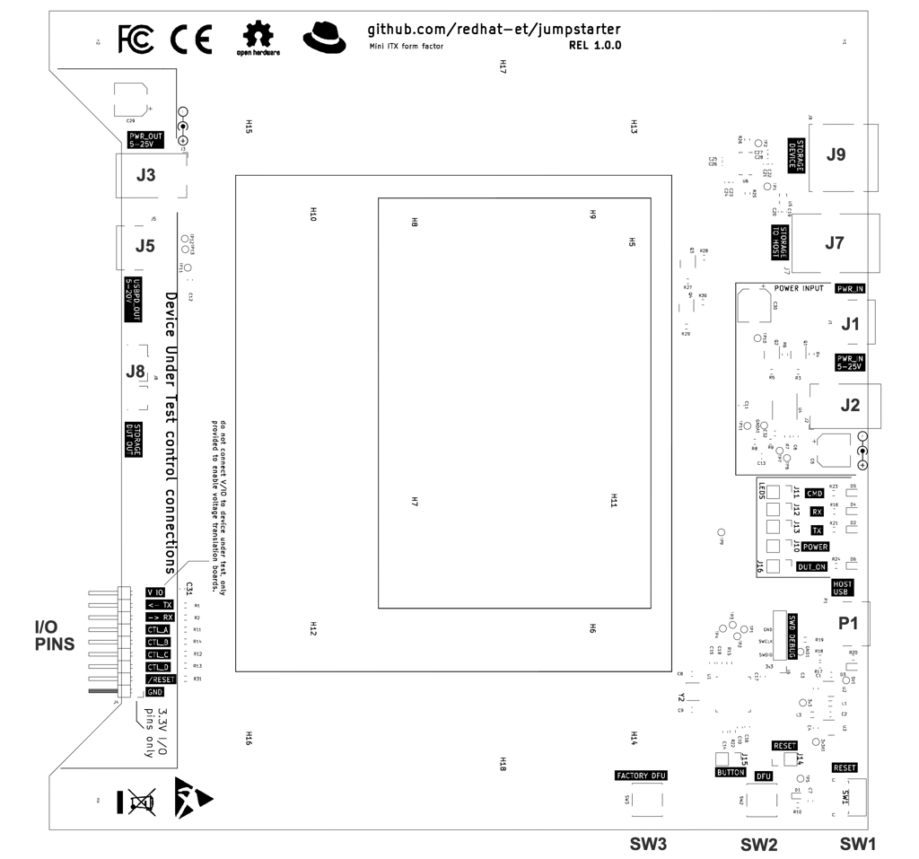
Device Under Test connections
Power
| Connector | Definition |
|---|---|
| J3 | J3 is a barrel jack connector that provides power output to the DUT. The source
of the power comes from J1. Warning: Do not use at the same time as J5 or J2. |
| J5 | J5 is a USB-C connector that provides power output to the DUT. The source of the
power comes from J2, USB-PD negotiation is connected to the power adapter on J2. USB-PD is a standard that allows negotiation of the voltage and current. Warning: Do not use at the same time as J3 or J1. |
Storage
| Connector | Definition |
|---|---|
| J8 | J8 is a USB3 micro B connector for storage. This connector provides access to the storage device that is connected to J9. One possible cable you can use in this connector is this one: link |
I/O pins
The I/O pins connector provides a 3.3V digital interface to the DUT, or any surrounding test hardware (like video signal generators, sensor emulators, or other elements).
Never use a HI/H/1 signal on an output when the target device is only 1.2, 1.8 or 2.5V, as this could damage the device.
Outputs are protected with a 100 ohm resistor which would avoid damage in most cases.
The V IO pin is provided to enable the use of voltage translation circuits if necessary.
| Pin | Definition |
|---|---|
| V IO | Provides a voltage reference for a voltage translation circuit |
| TX | Provides an output UART to the DUT, this is connected to the jumpstarter console. |
| RX | Provides an input UART from the DUT, this is connected to the jumpstarter console. |
| CTL_A | Provides a digital input/output which can be controlled by the jumpstarter software. The current convention is to use this pin for forcing devices into flashing mode, but it can be used for any purpose. |
| CTL_B | Provides a digital input/output which can be controlled by the jumpstarter software. |
| CTL_C | Provides a digital input/output which can be controlled by the jumpstarter software. |
| CTL_D | Provides a digital input/output which can be controlled by the jumpstarter software. |
| /RESET | Provides a reset output signal which can be controlled from the jumpstarter software. It's active low open collector output, this means that it will output a '0' when the reset is asserted, and it will be in HiZ when the reset is not. |
Power input connections
| Connector | Definition |
|---|---|
| J1 | J1 is a barrel jack connector where the power adaptor for the DUT must be connected. The
destination of this power is J3. Warning: Do not use at the same time as J5 or J2. And please note that the center pin is the possitive connection, power cannot be inverted. |
| J2 | J2 is a USB-C connector that receives power for the DUT from the power adapter. The
destination is J5, USB-PD negotiation is connected between J2 and J5. Please note that
there is a bug in the 1.0.0 version of the board, and the USB-C receptacle is not wired
properly, so in some cases you may need to flip the USB-C cable to get the connection or
power working, this applies to all USB-Cs on the board. Warning: Do not use at the same time as J3 or J1. |
Host connections
| Connector | Definition |
|---|---|
| P1 | P1 is a USB-C connector that provides power and control to the Jumpstarter microcontroller, once this is connected to the host jumpstarter must be detected by the kernel and a ttyACM device must be detected. |
| J7 | J7 is a USB3 B connector. This connector must be connected to the host, and it provides access to the storage device connected to J9. One possible cable you can use in this connector is this one: link |
| Other/notes | While not technically a part of the dutlink board, some DUTs need USB host access to allow flashing from the host, i.e. NVIDIA Jetson boards. In some cases multiple USB connections. |
Storage Device
| Connector | Definition |
|---|---|
| J9 | J9 is a USB3 A connector, in this connector a storage device must be connected, this device will be multiplexed between the host and the DUT. The HOST can flash it, and the DUT can boot or install from this device. Flashing speed will hugely depend on the storage device used, and while the dutlink-board has been designed for 10Gbps USB3.2 Gen2, the speed will depend on the storage device used as well as the cables connected to J8 and J7. To stay on the safe side 5Gbps devices are recommended. One possible device you can use for this purpose is: link |
Connection examples
Last modified January 25, 2024: Rename jumpstarter board to DUTlink (febb291)